
FemtoLCC
An ESP32-C6 based LCC node with four block driver channels and an isolated DCC input.
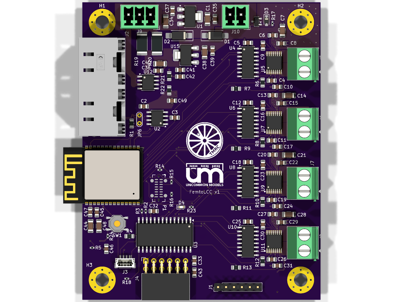
FemtoLCC is a four-layer accessory node for model railroad layouts. It joins an LCC/OpenLCB network over CAN, takes an opto-isolated DCC feed from the layout, and drives four independent block outputs from a single board.
What is on the board
| Block | Parts | Role |
|---|---|---|
| Controller | U14 ESP32-C6-WROOM-1 | Wi-Fi/BLE/802.15.4 capable RISC-V module running the node firmware |
| CAN / LCC | U2 MCP2562, J2 RJ45 | LCC bus transceiver and the standard RJ45 layout connector |
| DCC isolator | U12 HCPL-0630, R19/R20 2 kΩ 1 W | Dual optocoupler front end galvanically separating the DCC feed |
| Block drivers | U5/U7/U9/U11 DRV8874 | Four H-bridge channels, one per block output |
| Channel steering | U4/U6/U8/U10 SN74HC253 | Dual 4:1 multiplexers feeding the driver inputs |
| I/O expansion | U3 MCP23018 | I²C port expander for additional discrete I/O |
| Power | U15 NCP1117-5.0, U1 NCP1117-3.3, Q1 AO3401A | 5 V and 3.3 V rails with P-MOSFET reverse/ideal-diode path |
Connectors
J2 carries the LCC CAN bus on RJ45. J5–J8 are the four block driver outputs on
Phoenix MKDS 5.08 mm terminal blocks, with J9 and J10 on 3.5 mm Phoenix MCV headers
for the DCC and power feeds. P1 is a USB-C port, J1 a 6-pin UART header, J4 a PMOD
socket and J3 a 4-pin JST SH connector.
Getting started
The hardware page walks through what each block on the board does. Mechanical has the outline, mounting pattern and drill schedule, and ordering covers getting boards made.