
Power and battery
Idle power saving, the battery gauge and charge detection.
Idle tiers
The firmware saves power in stages as the throttle sits idle.
| Tier | After | What happens |
|---|---|---|
| Active | Any input | Backlight at full brightness, WiFi in minimum modem sleep |
| Dim | Dim delay | Backlight dimmed, WiFi in maximum modem sleep, RFID and keypad polled less often |
| Display off | Display-off delay | Backlight off and the LCD panel asleep. Once the loco is stopped, WiFi turns off and the ESP32 light-sleeps between polls |
| Power off | Power-off minutes, loco stopped | The loco is released, the session closed, and the unit powers down |
Any input returns to the active tier: the dial, touch, the button, the keypad, an RFID tag or a
serial command. During light sleep the unit wakes on dial rotation, the dial button, a screen
touch, or every LIGHT_SLEEP_INTERVAL_MS.
After a power off on battery, press the dial button to turn the unit back on. On USB power it deep-sleeps instead, and a screen touch reboots it. The backlight pin is held low through deep sleep, so the screen stays dark.
WiFi is never suspended, and the unit never light-sleeps or powers off, while the loco is moving or braking. A train running hands-off keeps receiving heartbeats.
Other savings
- The RFID reader’s 13.56 MHz field is only on for a few milliseconds per poll
(
RFID_POLL_ACTIVE_MS,RFID_POLL_IDLE_MS). - The keypad is polled on a schedule (
KEYPAD_POLL_ACTIVE_MS,KEYPAD_POLL_IDLE_MS). It buffers presses in its own FIFO between polls. - WiFi reconnects don’t block, and WiThrottle reconnects are retried every 5 seconds.
USB serial and light sleep
USB serial drops during light sleep. By default light sleep is skipped while a computer is
attached (LIGHT_SLEEP_SKIP_WHEN_USB_SERIAL). It still happens on battery or a plain USB
charger. If you plug a light-sleeping unit into a computer and the port doesn’t appear, touch the
screen or turn the dial first; it stays awake while the computer is attached.
Tuning
Brightness, delays and the power-off time are in the settings menu. The rest are in config.h:
ENABLE_WIFI_MODEM_SLEEP,ENABLE_WIFI_MAX_MODEM_SLEEP_WHEN_IDLEENABLE_WIFI_POWER_GATING_WHEN_DISPLAY_OFFENABLE_DISPLAY_PANEL_SLEEPENABLE_LIGHT_SLEEP_WHEN_DISPLAY_OFF,LIGHT_SLEEP_INTERVAL_MS,LIGHT_SLEEP_SKIP_WHEN_USB_SERIALENABLE_RFID_ANTENNA_DUTY_CYCLE,RFID_POLL_ACTIVE_MS,RFID_POLL_IDLE_MSKEYPAD_POLL_ACTIVE_MS,KEYPAD_POLL_IDLE_MSUI_MIN_REDRAW_INTERVAL_MS, which merges bursts of changes into one frameCPU_FREQ_MHZ, 240 by default. A full redraw takes about 17 ms of CPU at 240 MHz and about 104 ms at 80 MHz. Inputs are polled between frames, so a slow redraw makes the dial feel laggy. Drop to 80 only if you’d rather have the battery life than the responsiveness.
Battery gauge
| Battery gauge | Low battery |
|---|---|
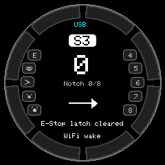 | 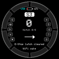 |
The Dial has a 1.25 mm 2-pin battery connector and a charger, but no battery voltage sense line, so a stock unit cannot read its battery. To show the battery level, add a resistor divider from the battery to an ADC1 pin on Port B:
BAT+ ---[ R1 100k ]---+--- GPIO1 (or GPIO2, Port B)
                      |
                   [ R2 100k ]
                      |
                     GND
Then in config.h set BATTERY_ADC_PIN to 1 (or 2) and BATTERY_DIVIDER_RATIO to
(R1 + R2) / R2, which is 2.0 for 100k/100k.
A battery icon with the percentage appears at the top of the screen. It turns yellow below 40%
and red at or below BATTERY_LOW_WARN_PERCENT, with a one-time low-battery beep. Set
BATTERY_SHOW_VOLTAGE to true to show millivolts while calibrating the ratio. With
BATTERY_ADC_PIN = -1 the indicator is hidden.
Charging and power source
According to the Dial schematic, the TP4057 charger’s CHRG and STDBY pins aren’t wired to the
ESP32, and the Grove 5V pin is boosted from the battery. A stock unit can’t tell whether it is
charging.
Without extra hardware it can only detect a USB host, meaning a computer sending USB frames. A plain USB charger or the DC terminal looks the same as battery power. The indicator row above the loco address shows:
| Label | Meaning | Needs |
|---|---|---|
USB | A computer is attached | Nothing |
PWR | External power detected | POWER_SENSE_ADC_PIN |
CHG | Charging | CHARGE_STATUS_PIN |
POWER_SENSE_ADC_PIN: wire a 100k/100k divider from the 5V input rail (StampS3 header pinM5V, net+5VIN, only live on USB or DC-terminal power) to GPIO1 or GPIO2. Don’t use the Grove 5V pin; it is powered on battery too.CHARGE_STATUS_PIN: solder a wire from the TP4057CHRGpin (pin 1, open drain, low while charging) to a free GPIO: GPIO39, 43 or 44 on the StampS3 header, or GPIO1 or 2. The firmware enables the internal pull-up.
With POWER_OFF_ONLY_ON_BATTERY (on by default) the idle power-off is skipped whenever external
power is detected. On a stock unit that only covers a computer, so on a wall charger it still
powers off after the idle time. The bat serial command prints the detected source and charge
state.